Site-scale watershed modeling
HUC14 catchment models nested in the watershed
A contaminated catchment is a few cells wide in a basin model. Site-scale rebuilds that one HUC14 fine enough to hold the plume, the wellfield, and the vadose zone above them — while the watershed model above it supplies the boundary.
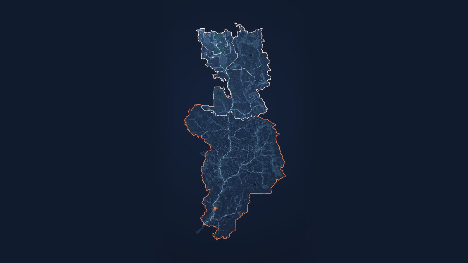
Most of what SWATGenX builds is basin-scale: a complete SWAT+ model for a HUC12 watershed, optionally coupled to a 3-D MODFLOW 6 aquifer. Site-scale points the same automated pipeline at one HUC14 catchment — the drainage area that actually holds the site, the plume, and the monitoring wells.
Where to cut a model, and how the model above it supplies the boundary, is a method question rather than a site one. It is worked through against already-built models — including where nesting is the wrong tool — on nested watershed modeling. This page is the case where the answer is a single catchment, and where the reason is almost always contaminant transport.
Why a nested site model
Start a site model
Model generation needs an account; cloud calibration comes with a subscription, if and when you want it. Contaminant, vadose-zone, and site-investigation studies that need finer than a basin-scale model start here — and if your study area is a reach or a management zone rather than a single catchment, start on nested watershed modeling instead.
Page updated 2026-07-13. Platform-generated, expert-finished.
FAQ
What is site-scale (HUC14) watershed modeling on SWATGenX?
A single-catchment SWAT+ model — optionally coupled to MODFLOW 6 — built for one HUC14 catchment and nested inside a coarser HUC12 watershed model that supplies its boundary conditions. It exists for contaminant fate-and-transport, vadose-zone, and site-investigation studies that need catchment-scale context a basin-scale model alone cannot resolve.
Why build a HUC14 site model instead of using the HUC12 watershed model?
A HUC12 model resolves a basin at about 250 m — right for regional water balance and streamflow, but a single contaminated catchment, wellfield, or source area is only a few cells wide at that resolution. Nesting a HUC14 site model keeps the study footprint on the catchment that holds the plume, the monitoring wells, and the vadose zone, while the HUC12 model still supplies inflow and groundwater context. Choosing where to cut in the first place — gauge, HUC12 outlet, or single catchment — and knowing when nesting is the wrong tool are covered on the nested watershed modeling page.
How do I simulate PFAS fate and transport at my site?
Generate the HUC12 watershed model over your area in the Watershed Explorer, then drill in and rebuild the single HUC14 catchment around your site, coupled to MODFLOW 6 for three-dimensional groundwater transport. The watershed model supplies the site model’s inflow and groundwater boundary conditions, while the National PFAS Soil Inventory and the groundwater lithology inventory populate the source term and aquifer automatically; site-specific boring and monitoring data then refine it. The mechanisms and a worked Wurtsmith example are documented on the PFAS fate-and-transport and watershed-to-site PFAS pages.
What is site-scale PFAS modeling?
Site-scale PFAS modeling builds a nested HUC14 catchment model — SWAT+ coupled to MODFLOW 6 GWT — inside a regional HUC12 watershed model. The fine grid resolves PFOA and PFOS transport from an AFFF or industrial source through the vadose zone into a three-dimensional aquifer plume, while the watershed model supplies inflow and groundwater boundary conditions. Demonstrated at Wurtsmith AFB with a 35-well validation network and explicit UZF/UZT vadose transport.